
Wiring Diagram for CTM Marine AC 4000E
TURN OFF ALL POWER BEFORE BEGINNING YOUR INSTALLATION
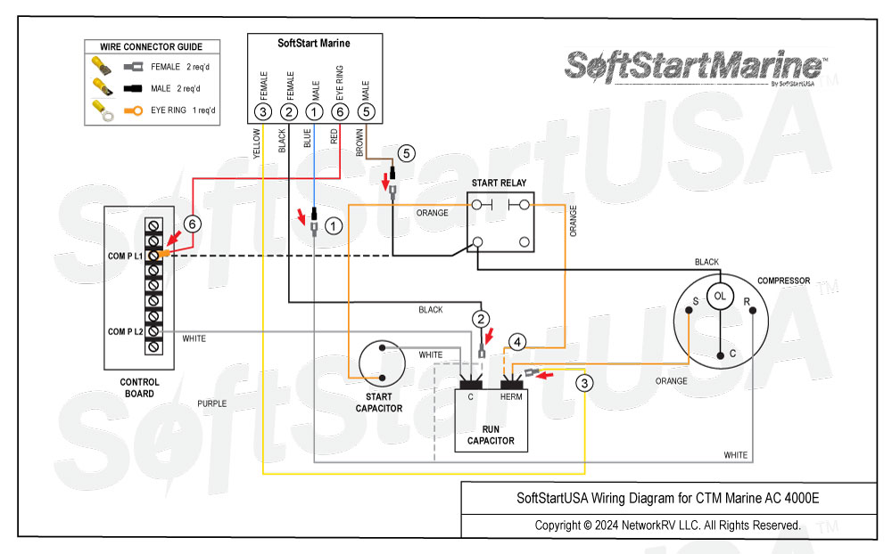
Wiring Diagram for CTM Marine AC 4000E
Instructions
TURN ALL POWER OFF BEFORE STARTING INSTALLATION.
Route all SoftStart wires into the electrical box. Then crimp Connectors onto all SoftStart wires as indicated in drawing.
Step 1. Follow White Compressor wire from Compressor to the “C” terminal of Run Capacitor. Disconnect it from terminal and connect end to Blue SoftStart wire. Seal connection with electrical tape.
Step 2. Connect Black SoftStart wire to the “C” terminal that the White Compressor wire was on.
Step 3. Connect Yellow SoftStart wire onto the HERM terminal which is next to the “C” terminal on the Run Capacitor.
Step 4. Disconnect the Orange wire from the HERM terminal that goes to the Start Relay. Seal the end with tape and drop it.
Step 5. Follow Black Compressor wire THROUGH Start Relay and TO the Control Board terminal COM P L1. Disconnect it from the Control Board and cut off its Eye Ring connector. Crimp female connector onto Black wire, then connect it to the Brown SoftStart wire. Seal connection with electrical tape.
Step 6. Connect Red SoftStart wire onto the Control Board terminal that the Black Compressor wire was on.
Secure all wires. Tape connections with electrical tape.
Turn Power and A/C Breaker on. Turn A/C to Auto Cool setting and set the thermostat as low as possible.
Look at SoftStart Marine RUN LED light (on left side). Green light should be “on”. Green light means the Compressor is running (there may be a full 3-minute “Test Mode” delay before Green light comes on). IF there is no Green light after 4 minutes, call SoftStart Tech Support for assistance.
After establishing Green light operation, re-install all A/C covers.
Turn A/C on, set near to outdoor temperature and run for 30 minutes. After 30 minutes, operate A/C normally.